Frequently asked questions#
We collected some common questions that we often get asked to create this FAQ section for a quick help lookup. If your question could not be answered, feel free to contact us.
How to ...?#
How do I change the flow range / fullscale value?
Refer to the analog output section. Change the option for the fullscale flowrate.
How do I input the linearization the best way?
Refer to the linearization section. The best way is to prepare a table with the two columns frequency and K-Factor in Microsoft Excel and use the copy-paste functionality to insert it into the Linearization Table Editor.
Connection#
I can't connect to the FU210 (using miniUSB) with the EasyLoader!
Make sure to supply the unit with 24 V DC. The USB connection does not supply the device with enough current to power it up.
I can't connect to a device (using RS232) with the EasyLoader!
- Make sure to have the
RxandTxwires crossed. Try swapping them. - Make sure to have 24 V supplied to the unit.
I can't connect to a device (in a table housing using USB-RS232 Adapter) with the EasyLoader!
- The RS232 wires are already internally crossed. Make sure to NOT use the Nullmodem-Adapter or Crossed-Cable.
- Make sure to have 24 V supplied to the unit.
After connecting with the EasyLoader I can't connect to OS 10.0 or the old version of EasyLoader anymore!
-
Try changing the COM-port settings of the OS 10.0 software to 38400 Baud, 7 bits, 1 Stop Bit, Even Parity. EasyLoader uses a faster baudrate for a faster data transfer process.
-
If you have the old version of VSE EasyLoader installed, open it and try right-clicking on the bottom connection toolstrip with the right COM-Port selected in the dropdown. Then select "Repair connection".
Files / Presets#
Why should I use the *.easyConf files if I can use the *.xml download function?
The *.xml files only contain the raw register values. The new *.easyConf filetype contains all configured settings including the original linearization values and the actual flowmeter name/values. This approach leaves more room for later editing of settings.
On the other hand, the *.easyConf file only contains the selectable settings. If you want to save the complete device state (with limit values, user inputs, etc.), you should rather use the *.xml filetype.
Whats the difference between the .par and .xml files?
Why can't I import my *.par file?
-
The
*.paris an older filetype used by the OS 3.2 user software, that was used many years ago to parametrize the display and F/U converter devices. It is neither compatible or supported for usage with the EasyLoader. If you still NEED to open it, contact us for more support. -
The
*.xmlfiletype is the new replacement format and contains the names and values of all device registers. The original settings like "Flowmeter name, K-Factor and Linearization table data" is not contained in this file use the*.easyConftype for this purpose.
I want to create a device configuration (*.easyConf) offline (without a device connection)!
Go to the About Easyloader page and select the option Simulate device connection for *.easyConf creation under the SETTINGS MENU. You will then be asked, which device you want to simulate and can continue creating the file with the Easy Configurator.
For a more detailed guide refer to this section in this manual.
Specifications / Analog out#
What are the maximum input frequencies of the devies?
- FU210: \(1 \textrm{ MHz}\)
- A350: \(1 \textrm{ MHz}\)
- A341: \(1 \textrm{ MHz}\)
What is the resolution of the analog output?
- FU210: \(16 \textrm{ bit}\)
- A350: \(16 \textrm{ bit}\)
- A341: \(14 \textrm{ bit}\)
To calculate the voltage/current step of the analogue output, use the following formula:
\(U_{step}=\frac{20 \textrm{ V}}{2^{14}} \approx 1.25 \textrm{ mV}\)
There is no actual change in resolution/steps if you change the analog range. The range will just be cropped. So if you for example change the analog output from +/- 10 V to 0..10 V, the effective analog resolution you will get for your 0..10 V range is 1 bit less 13 bits (for the A341).
What is the minimum reaction/refresh time of the analog output?
To achieve a minimum reaction time, the SAMPLING TIME and FILTER level must be as low as possible. With optimal settings, the following refresh intervals can be achieved:
- FU210 + A341: \(\approx 1 \textrm{ ms}\)
- A350: \(\approx 20 \textrm{ ms}\)
Display \(\neq\) Analog output
For display-devices, the analog output refresh time works independently of the configured display refresh interval.
Filters - What's the difference between the moving average and the exponential filter?
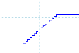
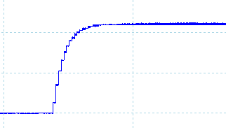
Imagining a step function on the input (e.g. \(0 \frac{\textrm{l} }{\textrm{min} }\) \(10 \frac{\textrm{l} }{\textrm{min} }\)), the moving average filter will result in a linear ramp function on the analog output. The exponential filter on the other hand will create an output function like a capacitor charging curve - at first moving fast towards the new value and later approaching more slowly to the value. The resulting rise time of the filter always depends on the chosen SAMPLING TIME. You can read more about how the filter works in the devices user manual.
Moving average filter
 `
`
Exponential filter

(The shown images show the analog output of an A350 with a sampling time of 50 ms and different filter settings)
Filters - The highest filter setting is not enough for me!
While keeping a high FILTER setting, adjust the SAMPLING TIME upwards until the desired analog output response/display response is achieved. Increasing the sampling time directly influences the filter dynamics.
FU252: Does the DIL2-switch have priority over the programming of the register ANALOGUE MODE?
This is describled in the user manual of the FU252. With setting 00, the format is based on the internal parameter ANALOGUE MODE. For all other DIL settings, the register value is irrelevant.
Why do I get so much signal noise from the analog output with low flowrates?
Generally the noise on the analog signal of the devices is in the high frequency range. These interferences are caused by the power supply itself and by the internal DC/DC converters.
Even though the noise content on the signal is pretty small, this noise floor is constantly there. It therefore makes sense to adjust the fullscale analog value to your applications maximum flowrate to get the best signal-to-noise-ratio from your analog output. It is also always recommended to keep cables short and well shielded.
The analog output shows 0V even though flow is present
- Check if your flow direction is negative. Try changing the
directionregister, swapping A and B wires, rotating the flowmeter or flipping the switch on the preamp. - Check if you have selected
Quadrature (2 ch.)by mistake even though your flowmeter only has one channel.
FU252: What is its reaction time and noise performance?
Reaction time:
-
The fastest possible reaction time of the FU252 is about \(150 \textrm{ µs}\). This is the reaction to the measured input frequency. The complete update time depends on the one hand on the level of the input frequency and on the other hand on the \(1 \textrm{ ms}\) cycle time of the internal program processing of the FU252.
-
Furthermore one should consider here the modulation range of the FU252. In the problem cases, the lowest flow ranges or frequency ranges are also assigned to the low analog output values, i.e. the update time here depends on the input frequency.
Noise performance:
- Generally the noise on the analog signal of the FU252s is in the high frequency range. These interferences are caused by the power supply itself and by the internal DC/DC converters. They appear as an additional noise voltage of \(\approx 20-40 \textrm{ mV}\) on the analog signal!
FU252: What does the INPUT FILTER register do?
The hardware filter is used to filter the signals. It works by varying the internal sampling frequency of the signals. However, this can lead to aliasing effects that can cause problems:
- Higher frequencies than the sampling frequency appear as lower frequency.
- The original frequency can be changed by the sampling frequency to a multiple of the sampling frequency.
It is usually used for spike filtering.
Note: Dont mix this up with the Filter settings of the EasyLoader!
EasyLoader specific questions#
Why is there a less than advertised number of linearization points available?
Why does it throw the error: 'too many columns'?
This is due to the fact that the first linearization register value always needs to be zero and the last one always needs to be the maximum value possible. This prevents the display value getting stuck if frequencies over the maximum linearized frequency occur, e.g. for detecting overload conditions. The other input fields that are shown can be completely filled with values. Therefore the number of available calibration points shrinks by two.
If you have a calibration certificate on hand with more than the allowed number of points, the best way to handle this is to skip some linearization points where the change of the \(K_{fact}\) value is the least or where the error curve is mostly linear.
The parametrization gets reset / does not save when I reconnect the 24V power. Why?
Make sure to have checked the option Permanent storage in the bottom options menu in the Device parameter editor. To simply send an EEPROM-Store command with the current settings, simply hit the UPLOAD button with the Permanent storage option checked - even without any register changes.
Why can't I do [...]? The software misses a feature!
The EasyLoader is meant for a simple and basic configuration of the device. Advanced settings can always be made manually using the Parameter Editor.
If you think your idea is also valuable for other users, feel free to send us a feature request ( contact persons).
Alternatively you can also try using the OS 10.0 software for this purpose. It is a legacy software that also features a register editor but is not specialized for easy usage with flowmeters. It can be downloaded from our homepage vse-flow.com.