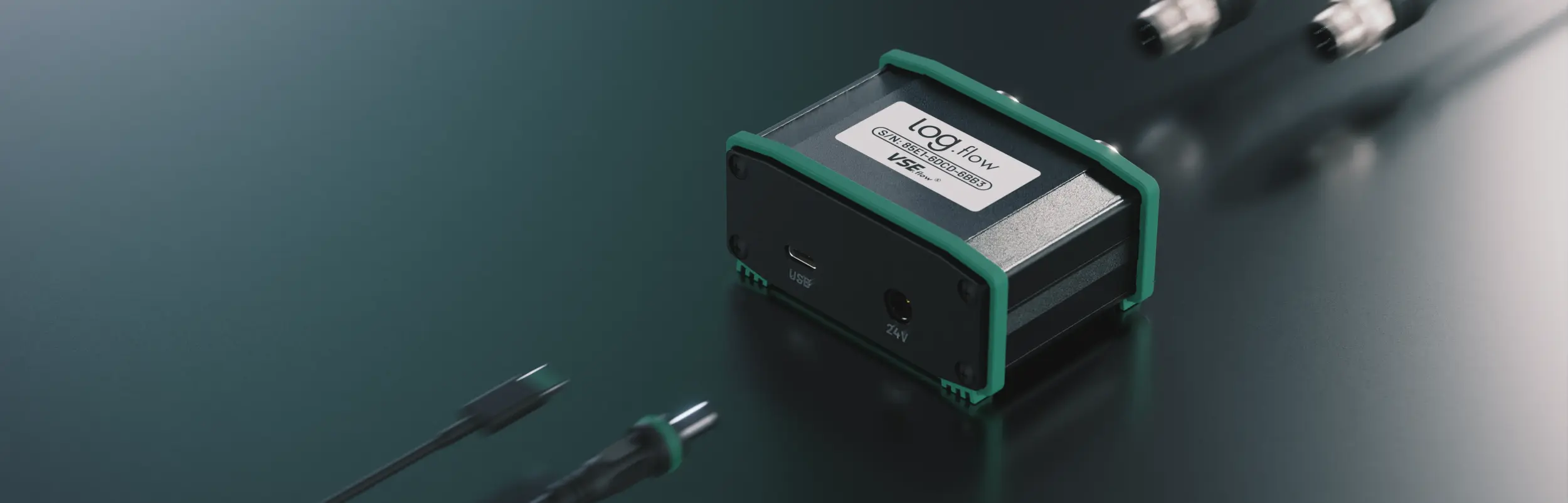
log.flow
Log.flow is the native EasyGraph datalogging hardware family. This page combines the connection guidance, variant-specific wiring, and device-side settings in one place.
Overview
Use log.flow when you want direct USB-based acquisition with high-precision frequency measurements and the tightest EasyGraph integration.
There are three hardware variants:

4881: dual frequency / pulse inputs
4881/V: one frequency / pulse input plus one analog voltage input
4881/I: one frequency / pulse input plus one analog current input
Connection
Before connecting any cable or voltage to the device, verify the correct hardware variant and use the matching connection diagram.
Available channels:
- Input 1: single or dual channel quadrature (HTL level 0..24 V)
- Frequency ( Flowrate)
- Pulse Count ( Volume)
- Input 2: single or dual channel quadrature (HTL level 0..24 V) plus additional input functions
- Frequency ( Flowrate)
- Pulse Count ( Volume)

Available channels:
- Input 1: single or dual channel quadrature (HTL level 0..24 V)
- Frequency ( Flowrate)
- Pulse Count ( Volume)
- Input 2: analog voltage input on pin 4 (max. 0..10 V)
- Analog Value ( Pressure, Temperature, other voltage sensors)
When connecting a sensor to the analog input, verify the pinout first. In practice you will often need an adapter cable that maps the sensor datasheet pinout to the log.flow connector.
Caution: 10 V voltage limit
Applying a HTL pulse signal or any voltage above 10 V to analog input 2 can damage the device.

Available channels:
- Input 1: single or dual channel quadrature (HTL level 0..24 V)
- Frequency ( Flowrate)
- Pulse Count ( Volume)
- Input 2: analog current input on pin 4 (max. 20 mA)
- Analog Value ( Pressure, Temperature, other current sensors)
When connecting a sensor to the analog input, verify the pinout first. Current-input wiring errors are more critical than voltage-input wiring errors.
Do not use a T-connector with current input
Do not connect an existing machine-side analog current loop in parallel with log.flow I. Current sensors must be connected in series. Internally the measurement uses a shunt from pin 4 to GND.
Info: 20 mA current limit
Connecting a HTL flowmeter or another low-impedance source to input 2 should be avoided. log.flow I detects persistent short-circuit conditions and disables the input until it is re-enabled in the device menu.

Activation
If you are connecting to a log.flow device for the first time, follow License Activation — Hardware Activation. The license is hardware-bound to the device and works without an internet connection.
Device menu
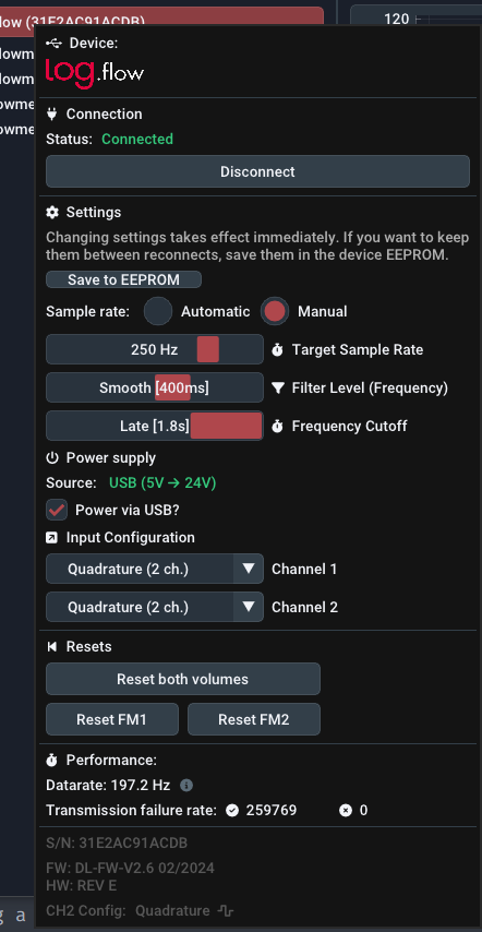
Open the device settings by performing a Right Button click on the connected log.flow in the device management panel. The usage of parametrization fields is explain in another section.
Parameter changes take effect immediately. Use Save to EEPROM only when the current setup has been validated and should persist on the hardware.
Measurement configuration
Sample rate: By default, the sample rate is set to Manual with a frequency of 250 Hz1. In Manual mode you can set the sample rate independently between 1 Hz and roughly 1000 Hz. You can also choose Automatic to set it dynamically based on the selected plot history. This avoids unnecessarily high sampling rates during long recordings.
Filter Level: The internal frequency filter trades response speed against smoothing. Lower settings respond faster and look noisier. Higher settings are steadier but slower.
| Filter Setting | Rise Time [ms] | Visualization |
|---|---|---|
Off |
0 | |
Dynamic |
10 | |
Medium |
100 | |
Smooth [default] |
400 | |
Heavy |
2000 | |
Extreme |
5000 |
Frequency Cutoff: This setting defines how long EasyGraph waits without signal edges before the measured frequency falls to zero. It is conceptually similar to the WAIT TIME parameter on A341, A350, and FU210 evaluation units. Lower cutoff times react faster to a stop but increase the minimum measurable frequency.
| Cutoff time [ms] | Cutoff setting |
|---|---|
| 250 | Early |
| 1000 | Normal |
| 1800 | Late [default] |
The minimum frequency \(f_{min}\) can be calculated from the cutoff time \(t_{wait}\) using:
Power supply configuration
log.flow supports three supply schemes:
- Internal 5 V to 24 V booster for powering attached flowmeters
- External 24 V injection through an M12 T-connector from the test bench or machine
- External 24 V wall supply via the DC jack for higher current demand
Enable the internal booster with Power via USB? in the device menu.
What is the internal boost converter?
The internal boost converter transforms the 5 V USB bus voltage up to 24 V to supply attached flowmeters — no external power adapter needed. Because USB current is limited, the output is capped at 50 mA @ 24 V total. Only connect low-power flowmeters when using this mode; exceeding the limit causes the circuit to overheat and lose regulation.
For reference: a TB2 testbox pulse generator draws ~30 mA, a VSI+ preamplifier draws ~36 mA.
The boost converter is especially practical on laptops or field setups where no bench power is available.
Tip: The voltage booster disables itself automatically
If an external power source is present, log.flow detects that state and disables the booster automatically.
Warning: Do not backfeed a test bench
Before using the included external power supply, make sure it does not feed back into the machine or test-bench 24 V rail. Otherwise the external supply may energize the bench unexpectedly when the bench itself is switched off.
Variant-specific notes
No additional power-specific options.
No additional power-specific options.
Short-circuit detection
log.flow I continuously monitors the analog current input. If a persistent short circuit is detected, the current path is disabled with a digital switch and EasyGraph shows a warning message.
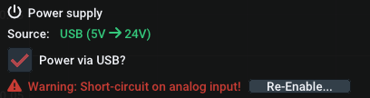
Use Re-Enable.. to restore the current path after the wiring fault has been removed.
Input configuration
The available input options depend on the hardware type.
Channel 1
- Quadrature (2 ch. on pin 2 + 4)
- Single channel (pin 2)
- Single channel (pin 4)
Channel 2
- Quadrature (2 ch. on pin 2 + 4)
- Single channel (pin 2)
- Single channel (pin 4)
- Reset on rising edge (pin 2)
- Reset on high level (pin 2)
- Reset on falling edge (pin 4)
- Reset on low level (pin 4)
The second channel on the standard log.flow variant adds external volume reset functionality for channel 1.
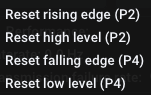
Connect a digital 24 V signal or switch to the second channel to trigger the reset. Edge-sensitive settings reset the value on a pin change. Level-sensitive settings keep the volume at zero while the condition remains true.
Tip: PNP input
The easiest switch wiring is between the 24 V line and the input pin. The log.flow input behaves like a PNP input because of the internal pulldown resistor.

Channel 1
- Quadrature (2 ch. on pin 2 + 4)
- Single channel (pin 2)
- Single channel (pin 4)
Channel 2
Channel 2 has a fixed analog voltage function on pin 4.
Channel 1
- Quadrature (2 ch. on pin 2 + 4)
- Single channel (pin 2)
- Single channel (pin 4)
Channel 2
Channel 2 has a fixed analog current function on pin 4.
Box contents
Order no. for
(Dual Frequency input): 4881
Order no. for
(Frequency + Analog voltage input): 4881/V
Order no. for
(Frequency + Analog current input): 4881/I
- log.flow measurement system
- USB-A to USB-C cable
- 24 V DC wall plug transformer
- 2x M12 connection cables
- 2x M12 T-Adapters Female-Male-Male
- EasyGraph software with download link and license key
- Transport case
Device specifications
Mechanical

| Parameter | Value |
|---|---|
| Size (l/w/h) | 71 x 79.5 x 35.5 mm |
| Weight | 140 g |
Electrical
| Parameter | Value |
|---|---|
| Supply voltage DC power port | 24 V DC nominal (18-26 V DC) |
| Maximum current draw (DC power/external) | Dependent on power supply |
| Maximum current draw (boost converter) | 50 mA (@24 V) total |
| Maximum recommended input frequency | ≤ 250 kHz |
| Maximum measurable input frequency | ~ 1-2 MHz |
| Maximum USB sample rate | 1000 Hz |
| Frequency measurement accuracy/error | ≤ 0,005% |
Digital Input Signal Levels
All frequency / pulse inputs operate at 24 V HTL signal levels. An internal pull-down resistor (~8 kΩ) holds each unconnected input at LOW.
| Parameter | Symbol | Value |
|---|---|---|
| Minimum input voltage | \(V_{min}\) | 0 V |
| Maximum input voltage (protected) | \(V_{max}\) | 26 V |
| High threshold (detected as HIGH) | \(V_{IH}\) | > 21 V |
| Low threshold (detected as LOW) | \(V_{IL}\) | < 7.8 V |
| Undefined range | — | 7.8 V … 21 V (avoid) |
| Internal pull-down resistance | \(R_{pd}\) | ~8 kΩ |

Compatible sensor output types
The inputs support Push-Pull and PNP signal sources. NPN sensors are not directly supported — use a level converter or an additional pull-up resistor (2–4.7 kΩ) between the signal pin and 24 V.
TTL incompatible
Standard log.flow units do not accept TTL-level sensors (0..5 V). The input high threshold is 21 V — a 5 V TTL high level is well below the input high level and will not work. Use a external level shifter before feeding the signal into the log.flow.
-
This was changed recently (from default=
Automatic) as experience shows that users perform recordings with a way too low sample rate by accident and lots of useful information gets lost. ↩